The RGB Matrix is the culmination of a couple of separate ideas and a whole bunch of experimentation, and it draws inspiration from quite a few different sources. After I built my first video synth modules I found myself generating a lot of images and patterns in primary colours – Red, Green and Blue – and realised that what I really wanted was a way to take one CV signal and individually control the amount of that signal that was sent to each of the three colour outputs. Basically something like a matrix mixer like the one that I’d seen in Ken Stone’s CGS Matrix Mixer for audio synths many years before, and so that module formed the basis of an early prototype of this module.
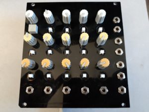
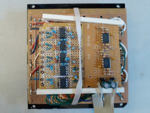
Here’s a picture of the original RGB matrix prototype, with knobs, pots and push-button switches all recycled from an old mixer and the whole thing held together by rubber bands! 🙂 The flying wires that you can just see sandwiched between the boards pick up a lot of crosstalk from each other, so it’s a good proof of concept but a bit noisy for real use. The sockets on the right side are the mix outs, plus a direct mix in for each channel (like the Direct In module in the final product). The socket in the bottom-right corner is a handy fixed +1V reference.
As I used it, I often found myself wanting to “mute” an input channel while I tweaked it, and this lead to an early incarnation of the input channel A/B destination switch. On another day I was using three LZX Cadet VI crossfader modules and a whole bunch of mults, mixers and attenuators to key between the mixer output and another external video luma source, and then later that same day playing with some old consumer video mixing gear (an MX-1). And so the idea of having separate A and B buses was born, allowing the operator to build up two separate video images in RGB space and then use a “key” input to cross-fade the mix between them.
The RGB Matrix has gone through a lot of revisions since that first prototype. Working out how best to connect the switches to the boards without having a bunch of awkward wires to solder was surprisingly difficult!
Of course you aren’t restricted to using the “Red”, “Green” and “Blue” outputs for just those colours. Each matrix output can be used for whatever signal mixing and distribution duties you want, and even be sent out to other modules and mixed back in again for interesting feedback effects. After all, the best things happen when you break from convention 🙂
If you’d like to build your own RGB Matrix, you can pick up a set of PCBs and Panels from the Visible Signals shop.